
Rayground is an online integrated development environment (IDE) for interactive demonstration and/or prototyping of ray tracing algorithms. Rayground is free for everyone, on any platform that has a WebGL2-compliant browser (no special plugins are required). In general, the user has the ability to create any number of new projects from scratch or copy an existing one from a variety of ray tracing projects made available from other users. Since Rayground IDE is web-based and online, users can work on it from anywhere, anytime.
The graphical user interface of Rayground is designed to have two discrete parts, the preview window and the shader editor. Visual feedback is interactively provided in the WebGL rendering context of the preview canvas, while the user performs live source code modifications.
At the core of Rayground there is a traditional ray tracing image synthesis pipeline, with several programmable stages via event handling shaders. It was designed with the aim to help users gradually understand how a ray tracer works, without getting distracted by the particular implementation of the framework or platform-specific characteristics. Since ray tracing is now tightly integrated into modern real-time rendering APIs, such as Vulkan, DirectX and OptiX, we follow a similar programming model. Rayground’s pipeline has five distinct configurable stages, namely Scene, Generate, Hit, Miss and Post Process, which are explained below, focusing on function rather than implementation. Thus, the shader editor consists of five tabs, corresponding to each one shader stage. A quick API reference is also provided under the "?" tab.

Our raytracing pipeline is consisted of various stages that are executed in parallel for each pixel of a Canvas and outputs a color. For each iteration of the pipeline, or frame, a pixel color is computed and blended with the previous values stored in an Accumulation Buffer. Results, after the blending operation, are displayed on a Canvas. The steps of our raytracing pipeline are illustrated below:

At first, geometric objects of the scene are specified in the Scene description stage. These objects are used to build data structures that accelerate ray intersection queries. The remaining 4 stages are programmable and are utilized to spawn and manipulate rays and in the end display the results on a Canvas. Each programmable stage has a different set of inputs and expects a different set of outputs. Rays are spawned in parallel for each pixel of the Canvas during the Generate stage using a ray generation shader. Each ray is defined by it's origin position, direction and length. Additionally, it has a payload value and an output color value that will be written to the pixel of the canvas that the ray originate from, when the ray has terminated. Rays are then intersected against the scene geometric objects and the intersection results are passed to the Hit or Miss stage depending on whether the ray intersected an object or not. On the Hit stage, the closest hit point on the ray is provided to a ray hit shader that performs calculations and updates the ray's output color and payload values. If nothing is hit, then a ray miss shader is executed. Both Hit and Miss stages output a new ray which is again tested against the scene geometry and a new ray hit or miss shader is invoked based on the intersection result. This recursive procedure is performed up until a specified number of recursion depth is achieved. Optionally, each ray recursion can be terminated, during the Hit or Miss stage and as a result get excluded from the recursive procedure. After this recursive precedure has ended, each final ray output color is blended with the pixel color of the previous result stored in the Accumulation Buffer. Finally, results are displayed to the Screen using a post processing shader during the Post Processing stage. We cover each stage separately in the following text.
Thr Rayground API is implemented using the WebGL2 standard, supporting shader programming via GLSL, thus providing a convenient and familiar code development interface. The user is encouraged to use built-in GLSL functions (e.g. dot, cross) and types (e.g. vec4, mat4). However, any use of the standard input and output variables of the GLSL programmable pipeline stages (e.g. gl_FragCoord) as well as samplers (e.g. sampler2D) may result in undefined behaviour and should be avoided. While certain functionality is common to all stages, there are also stage-specific input and output variables, which are described below in more detail.
1. Scene Declaration
This stage describes the 3D scene. Scene description is given in JSON format in the Scene editor tab. It is defined in a declarative format and therefore does not have any notion of input and output variables.
 {
  "settings": {
    "depth": 3
    .
    .
    .
  },
  "objects": [
    {  object0 properties  },
    {  object1 properties  },
    {  object2 properties  },
    {  object3 properties  },
    .
    .
    .
    {  objectN properties  },
  ]
}
The
The
These are:
quad cube sphere triangles
Material properties for each object are supplied using
This is an object description using all discussed properties.
  {
    "type": "quad",
    "model": [ 1, 0, 0, 0,
    0, 1, 0, 0,
    0, 0, 1, 0,
    10, 10, 10, 1 ],
    "translate": [ 0, 1, 1 ],
    "scale": [ 0.5, 0.5, 1 ],
    "rotate": [ 1, 0, 0, 90 ],
    "material_property0": [ 1, 0, 0, 0 ],
    "material_property1": [ 1, 0, 0, 0 ],
    "material_property2": [ 0, 1, 0, 0 ],
    "material_property3": [ 0, 0, 1, 0 ],
    "material_property4": [ 0, 1, 1, 0 ],
    "material_property5": [ 1, 0, 1, 0 ],
    "material_property6": [ 1, 1, 0, 0 ],
    "material_property7": [ 1, 1, 1, 0 ]
}
Following is a complete example JSON object of how to setup a Cornell Box scene.
  {
  "settings": {
    "depth": 10
  },
  "objects": [
    {
      "type": "quad", "translate": [ 0, 547.8, 0 ], "scale": [ 130, 105, 1 ],
      "rotate": [ 1, 0, 0, 90 ], "material_property0": [ 0.5, 0, 0 ]
    },
    {
      "type": "quad", "translate": [ 278, 274, 0 ], "scale": [ 556, 559, 1 ],
       "rotate": [ 0, 1, 0, -90 ], "material_property0": [ 0.05, 0.80, 0.05 ]
    },
    {
      "type": "quad", "translate": [ -278, 274, 0 ], "scale": [ 556, 559, 1 ],
      "rotate": [ 0, 1, 0, 90 ], "material_property0": [ 0.80, 0.05, 0.05 ]
    },
    {
      "type": "quad", "translate": [ 0, 548, 0 ], "scale": [ 556, 559, 1 ],
      "rotate": [ 1, 0, 0, 90 ], "material_property0": [ 0.80, 0.80, 0.80 ]
    },
    {
      "type": "quad", "translate": [ 0, 548, 0 ], "scale": [ 556, 559, 1 ],
      "rotate": [ 1, 0, 0, 90 ], "material_property0": [ 0.80, 0.80, 0.80 ]
    },
    {
      "type": "quad", "translate": [ 0, 0, 0 ], "scale": [ 556, 559, 1 ],
      "rotate": [ 1, 0, 0, -90 ], "material_property0": [ 0.80, 0.80, 0.80 ]
    },
    {
      "type": "quad", "translate": [ 0, 274, 280 ], "scale": [ 560, 565, 1 ],
      "rotate": [ 0, 1, 0, 180 ], "material_property0": [ 0.80, 0.80, 0.80 ]
    },
    {
      "type": "cube", "translate": [ 100.0, 82.5, -85.0 ], "scale": [ 165, 165.0, 165 ],
      "rotate": [ 0, 1, 0, 17 ], "material_property0": [ 0.8, 0.8, 0.8 ]
    },
    {
      "type": "cube", "translate": [ -100.0, 165, 85.0 ], "scale": [ 165, 330.0, 165 ],
      "rotate": [ 0, 1, 0, -17 ], "material_property0": [ 0.8, 0.8, 0.8 ]
    }
  ]
}
Programmable Stages
After the scene stage, the rest 4 stages of the Rayground pipeline are fully programmable. Generate and Post Process shaders execute the user's code in parallel for each pixel of the canvas.
The programmer should use
Certain functionalities and utilities are common to all stages but each stage has a specific set of input and output variables. Following are the functions and constants available to all shader stages:
Shader Stage Functions
| Type | Name | Description |
|---|---|---|
| vec4 | rg_Random(uint index, uint seed0, uint seed1) | Obtain 4 random values from a counter-based pseudo-random sequence. |
| bool | rg_TraceOcclusion(vec3 origin, vec3 direction, float tmax) | Send a ray to determine occlusion along the specified direction. |
Shader Stage Constants
| Type | Name | Description |
|---|---|---|
| vec2 | rg_Canvas | canvas resolution in pixels. |
| vec2 | rg_Pixel | pixel coordinates relative to the lower left corner of the canvas. |
| float | rg_Time | time in seconds since simulation start. Updates in every frame. |
| int | rg_Frame | current frame counter. |
| ivec4 | rg_Mouse | .xy current mouse position if clicked, else (-1, -1), .zw previous click position. Updates on mouse press. |
| int | rg_Depth | current ray depth iteration. Starts at 0 and gets incremented after each ray intersection wave. |
| uvec4 | rg_Seed | cpu generated seed values. Updated for each stage. |
| float | RG_RAY_MAX_DISTANCE | 1.e27 |
| float | RG_RAY_ACTIVE_FLAG | 1.0 |
| float | RG_RAY_INACTIVE_FLAG | 0.0 |
| float | RG_PI | 3.14159265359 |
| float | RG_TWO_PI | 6.28318530718 |
| float | RG_FOUR_PI | 12.5663706144 |
| float | RG_INV_PI | 0.31830988618 |
| float | RG_INV_TWO_PI | 0.15915494309 |
| float | RG_INV_FOUR_PI | 0.07957747154 |
One of the most important building blocks for ray tracing is random number generators (RNG). There is no "single" way to generate random numbers and the requirements depend on the task at hand.
Generating good random sequences in parallel on the GPU is generally a complicated task. To ease development, Rayground offers a pseudo random number generation function
that's based on the Philox counter-based RNG [1]. Usable seeds are provided by the backend in
vec4 get_uniform_random() {
  uint counter = uint(rg_Frame) * (uint(rg_Pixel.x) + uint(rg_Pixel.y) * uint(rg_Canvas.x) + 1u);
  return rg_Random(counter, rg_Seed.x, rg_Seed.y);
}
The idea is to request the random number at index
Ray Generate/Hit/Miss stages interface
Output properties that describe the ray passed to the next stage of the pipeline.
| Type | Name | Description |
|---|---|---|
| out vec4 | rg_Accumulation | output ray accumulation color values (.rgb values, .a additive blending factor). |
| out vec4 | rg_Payload0 .. 3 | output ray payload values. |
| out vec4 | rg_RayDirection | output ray direction (.xyz direction, .w max travel distance). |
| out vec4 | rg_RayOrigin | output ray origin (.xyz origin, .w RG_RAY_ACTIVE_FLAG or RG_RAY_INACTIVE_FLAG). |
| in vec4 | rg_PrevAccumulation | input ray accumulation color values. |
| in vec4 | rg_PrevPayload0 .. 3 | input ray payload values. |
| in vec3 | rg_PrevRayDirection | input ray direction |
| in vec3 | rg_PrevRayOrigin | input ray origin |
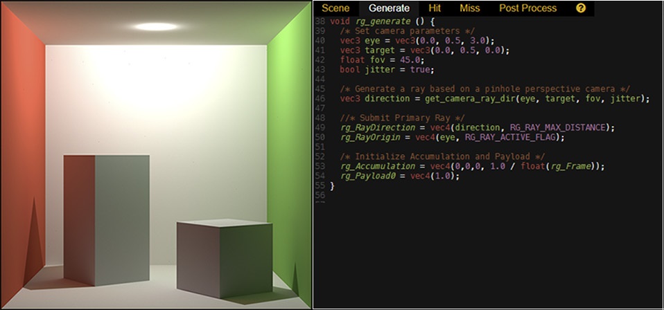
2. Ray Generation
The Ray Generation stage is the entry point for a particular scene. The function signature for this stage is
As the name suggests, this stage is responsible for generating the primary rays and initializing simulation values. A ray is defined with an origin point and a direction.
Each pixel must output to the
This is also the right place to initialize
If a constant update of the resulting image is desired, then
The typical structure for a ray generation program is shown below:
  void rg_generate() {
    vec2 canvas_size   = rg_Canvas;
    vec2 pixel_coords  = rg_Pixel;
    int  frame_index   = rg_Frame;
    .
    .
    .
    vec3 ray_direction = ...;
    vec3 ray_origin    = ...;
    .
    .
    .
    rg_RayDirection    = vec4(ray_direction, RG_RAY_MAX_DISTANCE);
    rg_RayOrigin       = vec4(ray_origin, RG_RAY_ACTIVE_FLAG);
    rg_Accumulation    = vec4(0.0, 0.0, 0.0, 1.0 / float(frame_index));
    rg_Payload0        = vec4(1.0);
}
Several Rayground builtins are shown in the above code snippet.
Notice how we make sure to mark the ray as an active with
3. Ray-Object Intersection
Hit event is where the most interesting work takes place. The Rayground API provides a lot of information regarding the surface intersection.
Ray Hit stage interface
Ray hit shader stage input/output variables and functions
| Type | Name | Description |
|---|---|---|
| void | rg_hit ( ) | entry point signature. |
| in vec3 | rg_Normal | geometric normal of the intersected primitive. |
| in vec3 | rg_Hitpoint | ray hit position in world space coordinates. |
| in vec3 | rg_BaryCoords | the barycentric coordinates on the intersection with the primitive. |
| in vec2 | rg_TexCoords | the interpolated texture coordinates of the intersected primitive. |
| in int | rg_MaterialID | the primitive's material ID. |
| in int | rg_ShapeID | the primitive's shape ID. |
| in int | rg_PrimitiveID | the primitive ID. |
| in float | rg_RayDistance | the ray segment length. |
| in vec4 | rg_MaterialProperty0 .. 7(int materialID) | the material properties, as specified in the scene description for the given material ID. |
  void rg_hit() {
    vec2 canvas_size   = rg_Canvas;
    vec2 pixel_coords  = rg_Pixel;
    int  frame_index   = rg_Frame;
    .
    .
    .
    vec3 ray_direction = ...;
    vec3 ray_origin    = ...;
    .
    .
    .
    rg_RayDirection    = vec4(ray_direction, RG_RAY_MAX_DISTANCE);
    rg_RayOrigin       = vec4(ray_origin, RG_RAY_ACTIVE_FLAG);
    rg_Accumulation    = vec4(0.0, 0.0, 0.0, 1.0 / float(frame_index));
    rg_Payload0        = vec4(1.0);
}
4. Ray-Object Miss
A ray miss event is triggered every time a ray does not intersect an object along a specific direction and a certain travel distance.
Miss kernels, offer the same capabilities as intersection kernels, but since there is no geometry hit, they do not have access to any
surface properties(e.g.
However, a miss shader is responsible for generating or terminating ray segments using
Similarly,
Miss shaders can be used to apply a background color or environment map.
  void rg_miss() {
  /* Properly set accumulation color and blending factor */
  rg_Accumulation = vec4(0.0, 0.0, 0.8, 1.0 / float(rg_Frame));

  /* Explicitly terminate ray */
  rg_RayOrigin = vec4(0,0,0, RG_RAY_INACTIVE_FLAG);
  rg_RayDirection = vec4(0.0);
}
5. Post Processing
The post processing stage gives global access to the accumulated image buffer from previous steps. This allows for various programmable filters to be applied on the final image.
The image is accessible through the
Post Processing stage interface
| Type | Name | Description |
|---|---|---|
| void | rg_post_process ( ) | entry point signature. |
| out vec4 | rg_PixelColor | final pixel color to be presented. |
| in rg_Image2D | rg_AccumulatedImage | 2D image buffer with the accumulated values (after blending operation). |
| in rg_Image2D | rg_Payload0Image | 2D image buffer with the payload0 values from the previous stage. |
| in rg_Image2D | rg_Payload1Image | 2D image buffer with the payload1 values from the previous stage. |
| in rg_Image2D | rg_Payload2Image | 2D image buffer with the payload2 values from the previous stage. |
| in rg_Image2D | rg_Payload3Image | 2D image buffer with the payload3 values from the previous stage. |
| in rg_Image2D | rg_FirstBounceRayOriginImage | 2D image buffer with the first generated ray origin. These values are provided by the backend if specified in the scene description. |
| in rg_Image2D | rg_FirstBounceRayDirectionImage | 2D image buffer with the first generated ray direction. These values are provided by the backend if specified in the scene description. |
| in rg_Image2D | rg_FirstBounceRayDepthImage | 2D image buffer with the first bounce depth (distance to the closest intersected primitive). These values are provided by the backend if specified in the scene description. |
| in rg_Image2D | rg_FirstBounceNormalsImage | 2D image buffer with the first bounce normals (the normal of the closest intersected primitive). These values are provided by the backend if specified in the scene description. |
| in rg_Image2Di | rg_FirstBounceMaterialID | 2D image buffer with the first bounce material ID (the material ID of the closest intersected primitive) stored in the R channel. These values are provided by the backend if specified in the scene description. |
| in rg_Image2Di | rg_FirstBounceTriangleID | 2D image buffer with the first bounce triangle ID (the triangle ID of the closest intersected primitive) stored in the R channel. These values are provided by the backend if specified in the scene description. |
| in vec4 | rg_ImageFetch2D (rg_Image2D image, ivec2 coords) | 2D image fetch from the specified pixel coordinates. |
| in ivec4 | rg_ImageFetch2Di(rg_Image2Di image, ivec2 coords) | 2D image fetch of integer data from the specified pixel coordinates. |
In its simplest form, a post processing kernel simply outputs the accumulated image to the final image.
  void rg_post_process() {
    rg_PixelColor = rg_ImageFetch2D(rg_AccumulatedImage, ivec2(rg_Pixel));
}
In this stage, the user can also request access to a series of special 2D image buffers corresponding to values from the first ray bounce, like
Keyboard Shortcuts
The following table gives an overview of the default Rayground keyboard shortcuts that are useful while working on shader editor.| Keystroke | Action |
|---|---|
| Ctrl-S | Compile & Run source code |
| Ctrl-Space | Upload Changes & Capture teaser image |
| Ctrl-D | Download source code |
| Ctrl-L | Export image (EXR format) |
| Ctrl-F | Find |
| Ctrl-G | Find next |
| Shift-Ctrl-G | Find previous |
| Shift-Ctrl-F | Replace |
| Shift-Ctrl-R | Replace all |
| Alt-G | Go to line |
| F11 | Toggle full screen editing |
| Esc | Exit full screen editing |
To get more familiar with Rayground we encourage users to see some of the existing samples that further showcase Rayground's capabilities.
Currently, the WebGL spec exposes only a subset of the functionality that a modern GPU has to offer which limits our available options. Stay tuned as we look forward to improving Rayground as we implement new solutions and additional GPU features become available.
Rayground would not have been possible without these amazing open-source technologies
[1] J. K. Salmon, M. A. Moraes, R. O. Dror and D. E. Shaw, "Parallel random numbers: As easy as 1, 2, 3," SC '11: Proceedings of 2011 International Conference for High Performance Computing, Networking, Storage and Analysis, Seatle, WA, 2011, pp. 1-12.